 ![I2C bus connection of RPI and Sension]
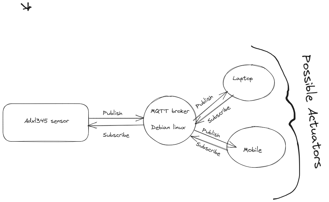
There are some useful guides on MQTT online. For example:
sudo apt install mosquitto
sudo apt install mosquitto-clients

The server will usually be executed automatically. In which case you should be able see that the server is bound to port 1883 on your Linux desktop machine:

You can see with netstat -at command
You need to edit the configuration file for the mosquitto server.
You can learn more about ADXL345 sensor from this link
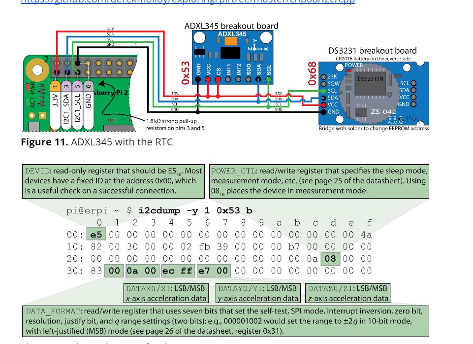
Electronics is out of context in this blog post so i'll wont go into details about I2C bus that enables connecting devices to rpi such as ADXL SENSOR in our project.But ill put a image below that can give you idea.
You can learn more about I2C(Inter-Integrated Circuit)
Here is figure how you can establish I2C connection with rpi and two sensors(ADXL345,DS3231)
![I2C bus connection of RPI and Sension]
In this part of the blog we will develop an application that captures external data through sensor and sends the data to broker.Thus publishing the external data
As an enthusiast of Object-Oriented Programming (OOP), you appreciate the benefits of designing systems with clear abstractions and well-defined interactions. In this guide, we will explore how to apply OOP principles while connecting and manipulating a device connected to the I2C bus on a Linux-based operating system. Understanding the Linux file-system and its hierarchical structure will allow us to control various aspects of the operating system, including user privileges, web configurations, and memory allocation.
Linux File-System Basics: Linux, including Raspberry Pi OS (formerly Raspbian), uses a hierarchical file-system that provides a unified way to access and manipulate various components of the operating system. Almost everything, including hardware devices, is represented as files or directories, creating a seamless interface for both the user and applications.
I2C Device Interaction: The Inter-Integrated Circuit (I2C) protocol is commonly used to communicate with peripheral devices, such as sensors and displays, in embedded systems like the Raspberry Pi. On Linux, I2C devices are accessible through special files in the /dev directory, such as /dev/i2c-*. By reading and writing to these files, we can interact with I2C devices programmatically.
OOP Design for I2C Communication: Applying OOP principles to I2C communication will allow us to encapsulate the low-level details of I2C interactions within classes or objects, providing a clean and reusable interface. We can create an I2CDevice class that abstracts away the complexities of device addressing, read/write operations, and error handling. This class can act as a driver to interact with specific I2C devices.
Device Communication and Abstraction: By leveraging OOP, we can create higher-level classes specific to each I2C device, encapsulating the device's functionality and operations. For example, we can have a TemperatureSensor class that handles readings from a temperature sensor, and a Display class to manage data display on an I2C-driven screen. These classes communicate with the underlying I2CDevice class, providing a well-structured interface for application development.
Linux File-System Manipulation: OOP design allows us to organize code logically, but we can also utilize the Linux file-system for configuration and management tasks. For example, we can use configuration files in the /etc directory to set up web server settings or manage user privileges. Additionally, proper memory allocation and control can be achieved by using system calls and memory management functions.
By combining the power of OOP design and Linux file-system manipulation, we can create efficient and organized code for interacting with I2C devices on a Raspberry Pi or any Linux-based system. This approach enables us to build modular and maintainable systems that effectively control and communicate with external hardware while taking advantage of the Linux environment's flexibility and robustness.*
Here is a link of the code for establishing connection for I2C bus
As i said with OOP desing architecture our based class will be called I2C bus allowing us to maintain reliable connection and manipulate device registers of the external devices that is on the I2C bus.
Here is a link of allowing us to CRUD operations on registers of adxl345
Understanding the Code:
The provided C++ code implements a class called "ADXL345" that facilitates communication with the ADXL345 accelerometer over the I2C bus. Let's go through the main aspects of the code:
I2C Communication: The ADXL345 class inherits from the "I2CDevice" class, which encapsulates the low-level I2C communication. The I2CDevice class handles reading and writing to I2C registers, making it easier for us to focus on the accelerometer functionality.
Device Registers: The code defines constants representing the ADXL345's register addresses (e.g., DEVID, THRESH_TAP, etc.). These registers are memory locations within the accelerometer where data and configuration settings are stored.
Sensor State Reading: The "readSensorState()" method reads the accelerometer's registers and extracts the X, Y, and Z-axis acceleration values. It also verifies the correct sensor ID to ensure successful communication with the ADXL345.
Pitch and Roll Calculation: The "calculatePitchAndRoll()" method uses the acquired acceleration values and the accelerometer's resolution and range settings to compute the pitch and roll angles. These angles represent the orientation of the sensor in degrees.
Setting Resolution and Range: The code includes methods to set the resolution and gravity range of the ADXL345. The resolution can be set to either "HIGH" or "NORMAL," with the "HIGH" resolution available only for the +/- 16g range.
Data Display and Storage: The "displayPitchAndRoll()" method continuously reads the sensor state and calculates pitch and roll angles. It stores the values in vectors for further analysis or display.
By following this guide, you've learned how to interact with the ADXL345 accelerometer on a Raspberry Pi using the I2C protocol. The provided C++ code simplifies the communication process and allows you to read acceleration data and calculate orientation angles easily. You can further extend this project to integrate the accelerometer data into your own applications, such as motion-based control or tilt sensing in IoT projects. Happy exploring with the ADXL345 accelerometer!
C++ code that demonstrates how to integrate the ADXL345 accelerometer with MQTT communication on a Raspberry Pi. The code uses the Eclipse Paho MQTT C library to publish data from the accelerometer, including CPU temperature, pitch and roll values, to an MQTT broker.*
Library and Header Inclusions:
The code includes several C++ and C headers, such as
MQTT Broker Configuration: The code specifies the address of the MQTT broker, client ID, authentication method, and authentication token. These configurations are essential for the Raspberry Pi to connect to the broker.
CPU Temperature Reading: The getCPUTemperature() function reads the CPU temperature from the file /sys/class/thermal/thermal_zone0/temp and returns the value in degrees Celsius.
JSON Formatting: The jsonformat() function receives a map containing pitch and roll values from the ADXL345 accelerometer. It formats this data into a JSON string using the json-c and jsoncpp libraries.
MQTT Client Setup: The code initializes the MQTT client and sets up last-will message options using MQTTClient_willOptions. If an unexpected disconnection occurs, the last-will message will be sent to the specified topic.
ADXL345 Initialization: The ADXL345 accelerometer is initialized with resolution and range settings, and the displayPitchAndRoll() method is called to obtain pitch and roll values from the sensor.
Data Publication Loop: Inside the main loop, the CPU temperature, pitch, and roll values are obtained from the ADXL345 accelerometer. The current timestamp is also captured. This data is formatted into a JSON payload using sprintf() and published to the MQTT broker using MQTTClient_publishMessage().
MQTT Connection and Disconnection: The code establishes a connection to the MQTT broker using MQTTClient_connect(), waits for the publication to complete, and then disconnects using MQTTClient_disconnect().
By following this guide, you've learned how to integrate the ADXL345 accelerometer with MQTT communication on a Raspberry Pi. The C++ code provided enables you to read pitch and roll values from the accelerometer, obtain the CPU temperature, and publish this data as JSON payloads to an MQTT broker. This integration opens up possibilities for various applications, such as real-time monitoring, remote sensing, or IoT projects. Happy exploring with MQTT and ADXL345 accelerometer data on your Raspberry Pi!
Here you can find the Code for subscriber module
C++ code that acts as an MQTT subscriber on a Raspberry Pi and simultaneously controls a GPIO pin to turn an LED on or off based on received MQTT messages. The code uses the Eclipse Paho MQTT C library to communicate with an MQTT broker and the WiringPi library to control the GPIO pin.
Library and Header Inclusions:
The code includes various C and C++ headers such as <stdio.h>, <stdlib.h>, <string.h>,
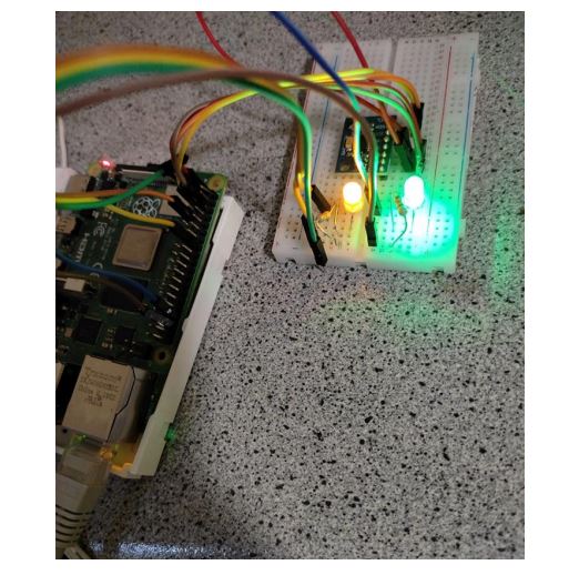
GPIO Control Functions: The code defines functions turnlightof() and turnlighton(), which control an LED connected to GPIO pin 23. These functions turn the LED off and on, respectively, by interacting with the GPIO file system at /sys/class/gpio/.
JSON Parsing Function: The json_parse1() function is responsible for parsing the JSON payload received from the MQTT broker. It extracts the "CPUTemp" value, "Pitchvalues" array, and "Rollvalues" array from the JSON object. Based on the values of "Pitchvalues," it decides whether to turn the LED off or on.
MQTT Callbacks: The code defines three callback functions for MQTT: msgarrvd(), connlost(), and delivered(). These functions are called by the MQTT client library when a message is received, the connection is lost, or a message delivery is confirmed.
MQTT Client Setup: The MQTT client is created using MQTTClient_create(), and connection options are initialized. The client connects to the MQTT broker using MQTTClient_connect(). If the connection is successful, the client subscribes to the specified topic using MQTTClient_subscribe().
Message Loop and GPIO Control: The code enters a message loop using getchar() and waits for the user to press 'Q' or 'q' to quit. During the loop, the client waits for incoming messages. Once a message is received, the msgarrvd() function is called, which parses the JSON payload and controls the LED based on the pitch values.
MQTT Client Disconnect: When the user quits the program, the client disconnects using MQTTClient_disconnect() and is then destroyed using MQTTClient_destroy().
In this blog post, we explored a system architecture that combines MQTT communication and GPIO control on a Raspberry Pi. We developed two separate C++ programs: one for publishing sensor data to an MQTT broker and the other for subscribing to MQTT messages and controlling an LED based on received data. The system allows us to remotely monitor sensor data and control an LED using the MQTT protocol.
The system architecture consists of two main components:
MQTT Publisher:
The MQTT publisher code reads data from an accelerometer sensor (ADXL345) connected to the Raspberry Pi. It formats the sensor data into a JSON object, containing pitch and roll values, and CPU temperature. The MQTT publisher uses the Eclipse Paho MQTT C library to connect to an MQTT broker and publish the JSON payload to a specific topic. The MQTT publisher runs on the Raspberry Pi and periodically sends sensor data to the MQTT broker. MQTT Subscriber with GPIO Control:
The MQTT subscriber code acts as an LED controller that listens for MQTT messages from the broker. When a message is received, the subscriber parses the JSON payload and extracts the pitch values. Based on the pitch values, the subscriber turns an LED connected to GPIO pin 23 on or off using the WiringPi library. The MQTT subscriber also reports the CPU temperature received in the JSON payload. The subscriber continuously listens for incoming MQTT messages and controls the LED accordingly. Overall Working:
The ADXL345 sensor connected to the Raspberry Pi measures pitch and roll values, and the C++ MQTT publisher code reads this sensor data. The MQTT publisher formats the sensor data into a JSON object and sends it to the MQTT broker. The C++ MQTT subscriber code is running in parallel, subscribing to the same MQTT topic used by the publisher. When the MQTT subscriber receives a message, it parses the JSON payload to extract the pitch values. Based on the pitch values, the subscriber turns the LED connected to GPIO pin 23 on or off. The MQTT subscriber also reports the received CPU temperature. The system allows users to remotely monitor the pitch values, CPU temperature, and control the LED from any MQTT client. Conclusion:
The combination of MQTT communication and GPIO control on a Raspberry Pi offers exciting possibilities for IoT applications. This system architecture demonstrates how to build a simple but practical IoT system where sensor data can be shared with multiple devices through an MQTT broker. By integrating GPIO control, the system allows users to interact with physical devices remotely.
From here, you can expand and adapt the system to various use cases, such as home automation, environmental monitoring, and industrial automation. The power of MQTT and the Raspberry Pi enables you to create sophisticated IoT applications that connect and control a wide range of devices and sensors. Happy exploring!